Overview
This page will give a brief overview of what findus (aka the fault-injection-library) and the PicoGlitcher is, what it can be used for and where to go from here.
Fault-Injection
Fault injection is a group of attacks in which external influences are used to cause faults in a system and thereby influence the behavior of the system. In the simplest case, this can be an input mask on a web application that is not correctly secured against incorrect input. However, fault injection attacks usually also involve some kind of side-channel attack. This means that the fault is not caused by the usual channels (e.g. the input screen on the web application), but by a second channel. In the case of microcontrollers or embedded systems in general, the power supply or the clock generators on the board are used as a side channel to provoke error states.
Voltage Glitching
In voltage glitching, the voltage supply to the chip is reduced for a very short time (in the order of nanoseconds to a few microseconds) to such an extent that processes in the chip no longer function correctly. Energy is required for certain operations in the chip. If this energy is not available, the operation is not carried out or is carried out incorrectly. Writing or erasing a memory cell, for example, cannot take place if there is not enough energy (i.e. in the simplest case, the supply voltage) available.
If the power supply is reduced at the time when a CPU register is written, no data or an incorrect value is written to the register. This can be particularly useful as an attack vector if the microcontroller has read-out protection. With read-out protection, the flash content is protected by checking if certain register values are set. These register values are not usually located in the firmware on the flash, but in a separate memory area, so-called fuses. If the microcontroller wants to check whether the read-out protection is set, these fuses must be read out and copied to an internal CPU register. If the power supply is lowered during this copying process so that the internal CPU register is written to incorrectly, the read-out protection can potentially be bypassed.

The parameters for such attacks are the time delay from a trigger condition to the glitch itself ("delay") and the duration of the glitch ("length"). The trigger condition can be anything, for example switching on the power supply, removing the reset signal or certain states in the data transmission.
What is findus?
Findus (aka the fault-injection-library) is a toolchain to perform fault-injection attacks on microcontrollers and other targets. This library offers an easy entry point to carry out fault-injection attacks against microcontrollers, SoCs and CPUs. With the provided and easy to use functions and classes, fault-injection projects can be realized quickly with cheap and available hardware.
Findus supports the ChipWhisperer Pro, the ChipWhisperer Husky and the PicoGlitcher. More information about the ChipWhisperer Pro and the ChipWhisperer Husky can be found on https://chipwhisperer.readthedocs.io/en/latest/index.html.
What is the Pico Glitcher v1?
The Pico Glitcher is a device similar to the ChipWhisperer Pro and the ChipWhisperer Husky. The Pico Glitcher is capable of generating voltage glitches very precisely. It also has several options for trigger generation, i.e. the Pico Glitcher can trigger on rising or falling edges, or even on patterns in a data transmission (for example on a specific UART word).
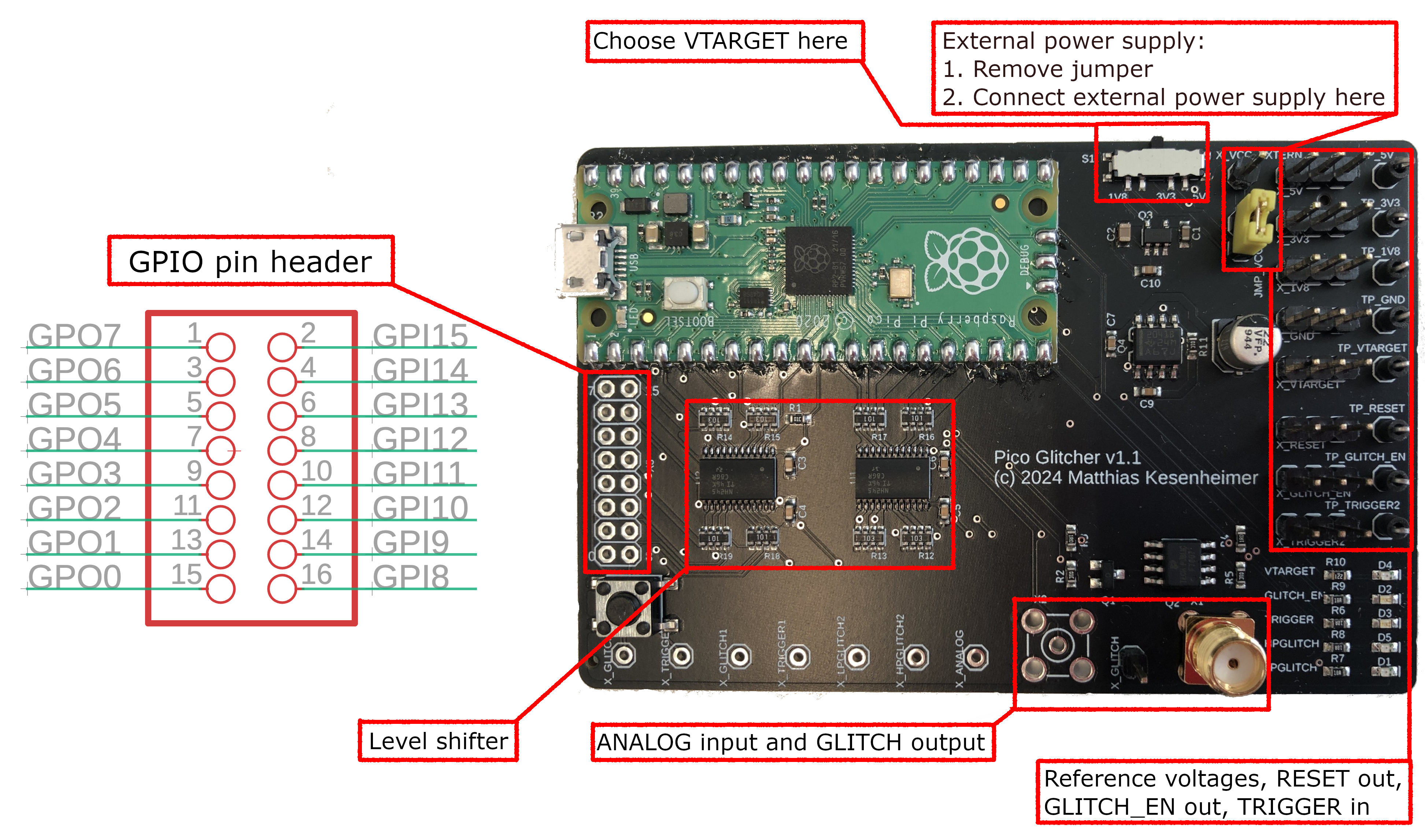
The hardware is based on the Raspberry Pi Pico, a low-power and a high-power MOSFET for glitch generation and other components for power supply. Level shifters ensure that the Pico Glitcher can handle a wide range of reference voltages, i.e. the Pico Glitcher is not limited to a fixed logic level.
Three tapping points are available for reference voltages: 1.8V, 3.3V and 5V. These can be used to supply the target or to provide reference voltages for external circuits. The voltage on the VTARGET pin header can be switched on and off via the findus library, which is useful for performing a hard reset on the target (power-cycle). The VTARGET pinouts can also be supplied by an external power supply unit. To do this, the JMP_VCC_INTERN jumper must be removed. The external power supply is then applied to the VCC_EXTERN pin.
An additional pin header is connected to the remaining GPIO pins of the Raspberry Pi Pico via level shifters. These can be programmed for further inputs and outputs as required. For example, further triggers can be created on these pin headers or protocol translators can be implemented.
Glitches are generated by two crowbar transistors. A 'IRLML2502' MOSFET is used for generating low-power glitches, the second 'SI4134DY' MOSFET can switch up to 50 Amperes. Depending on the application, one or the other transistor may be suitable. The transistors can be selected via the findus library. For most applications, the low-power MOSFET is sufficient and even generates sharper glitches (with steeper edges) than the high-power MOSFET. However, if larger currents need to be dissipated, for example if large capacitors are installed on the target, the high-power MOSFET is the better choice.
Status LEDs also indicate the current status of the board: Whether the target voltage is being generated, whether the glitcher is armed, or whether a trigger signal is present, etc.
Pico Glitcher v2
Compared to hardware revision 1, several new features have been added in revision 2. However, the basic usage is the same and the scripts for version 1 will also (likely) work for version 2 [1].

The hardware is similar to the Pico Glitcher v1 (based on the Raspberry Pi Pico, high-power MOSFETs for glitch generation, level shifters to ensure compatibility over a wide voltage range etc.).
The pin assignment of the GPIO header has changed due to PCB routing optimization.
These pins still can be programmed for further inputs and outputs as required. For example, further triggers can be created on these pin headers or protocol translators can be implemented.
Input pins GPIO16 - GPIO19 are connected to the Raspberry Pi Pico without a level shifter and can be used bi-directionally.
A new input stage (EXT1 and EXT2) has been added to the board which can be used to filter out noise and other disturbances, see section Schmitt Trigger EXT inputs.
The multiplexing output can be used to quickly switch between different voltage levels and to supply the target board with power. Up to four different voltage levels can be configured and switched between (see section Multiplexing).
Pico Glitcher v3
More improvements have been made to the Pico Glitcher version 3.

The summary of changes are:
- The Pico Glitcher version 3 is based on the Raspberry Pi Pico 2: higher clock speed, better accuracy in glitching attacks, more power!
- Improved power supply: You can now choose from four different voltages to interface with various microcontrollers: 1.2V, 1.8V, 3.3V, and 5V.
- Improved Schmitt trigger inputs provide even better and more reliable triggering.
Everything else is unchanged: Two high-power MOSFETs for crowbar glitch generation, and two level shifters to ensure compatibility over a wide voltage range. An Schmitt Trigger input stage (EXT1 and EXT2) can be used to filter out noise and other disturbances via adjustable Schmitt Triggers. The multiplexing output can be used to quickly switch between up to four different voltage levels and to supply the target board with power.
Compared to the original Raspberry Pi Pico, the Pico 2 is simply a better platform for voltage glitching. The most obvious advantage is performance. The Pico 2 runs at a significantly higher clock speed, which directly improves timing resolution. In glitching attacks, timing is everything. Finer timing granularity means you can place glitches more precisely relative to the target's execution, which increases both reliability and repeatability.
The improved power supply makes the Pico Glitcher far more flexible when attacking real-world targets. Modern microcontrollers operate at a wide range of core and I/O voltages, and voltage glitching is most effective when the glitch amplitude closely matches the target's supply rail. By supporting 1.2 V and 1.8 V directly, the Pico Glitcher can interface cleanly with low-power and high-performance MCUs without level shifters or external regulators.
The HYS potentiometer of the EXT2 input (see Schmitt Trigger EXT inputs) is used to adjust the hysteresis of the Schmitt trigger input EXT2. It controls the difference between the upper and lower switching thresholds. By changing this difference, it directly determines how much the input signal must move before the output changes state.
Continue reading getting started to learn more about how to set up your Pico Glitcher.
[1]: If not, please submit an issue at https://github.com/MKesenheimer/fault-injection-library/issues.