Customize your Pico Glitcher
In some cases the functionality findus provide will not be sufficient and you have to write your own code.
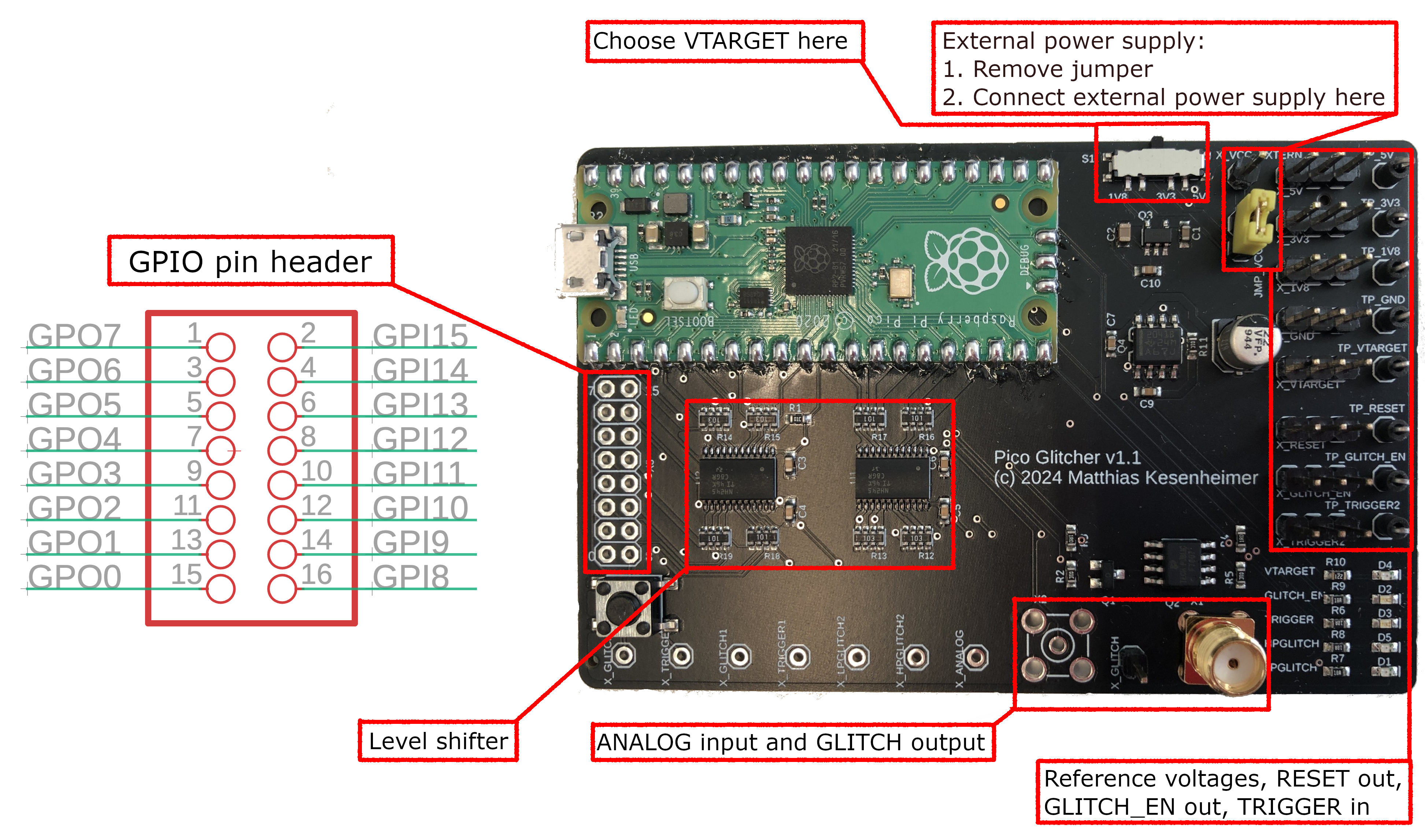
Pico Glitcher v1 GPIO pin overview
The Pico Glitcher v1 is built from these components:
The GPIO pins of the Raspberry Pi Pico are connected to the following outlets:
| GPIO Pin | Function |
|---|---|
| 0 | RESET (with level shifter) |
| 1 | GLITCH_EN |
| 2 - 7 | unused outputs (with level shifter) |
| 8 - 14 | unused inputs (with level shifter) |
| 15 | TRIGGER (with level shifter) |
| 16 | high-power glitch output |
| 17 | low-power glitch output |
| 18 | TRIGGER (without level shifter), currently unused |
| 19 | Glitch output (without level shifter), currently unused |
| 20 | VTARGET_EN: used to enable and disable the target voltage |
| 21 | VTARGET over current input, currently unused |
| 22 | unused |
| 26 | Analog input |
| 27 | unused |
| 28 | unused |
Pico Glitcher v1 GPIO pin header
If you want to write code for additional communication protocols, such as a UART-to-USB adapter, or an SPI-to-USB adapter, then the unused GPIO pins are perfect for that.
The output pins with level-shifting are GPIO2 - GPIO7. For inputs the pins GPIO8 - GPIO14 can be used.
Pico Glitcher v2 and v3 GPIO pin overview
Of course, the second revision of the Pico Glitcher can also be modified to suit your needs. Unfortunately, for better routing on the PCB and with added features, the GPIO pin assignment is different to version 1. Hence, code written for version 1 will likely not run on version 2.
The Pico Glitcher v2 is built from the following components:

And the high-level overview of the Pico Glitcher v3 is shown below:

The GPIO pins of the Raspberry Pi Pico are connected to the following outlets:
| GPIO Pin | Function |
|---|---|
| 0 | MUX1: Output 1 to multiplexer |
| 1 | MUX0: Output 0 to multiplexer |
| 2 | RESET (with level shifter) |
| 3 | GLITCH_EN (with level shifter) |
| 4 - 9 | unused outputs (with level shifter) |
| 10 | EXT2: Trigger input 2 with adjustable Schmitt Trigger |
| 11 | EXT1: Trigger input 1 with adjustable Schmitt Trigger |
| 12 | high-power glitch output |
| 13 | low-power glitch output |
| 14 | TRIGGER (with level shifter) |
| 15 | unused input (with level shifter) |
| 16 - 19 | unused in- and outputs (without level shifter) |
| 20 - 21 | unused inputs (with level shifter) |
| 22 | VTARGET_EN: used to enable and disable the target voltage |
| 26 | Analog input connected to glitch out line |
| 27 | Analog input connected to EXT1 input, currently unused |
| 28 | Analog input connected to EXT2 input, currently unused |
Pico Glitcher v2 and v3 GPIO pin header
If you want to write code for additional communication protocols, such as a UART-to-USB adapter, or an SPI-to-USB adapter, then the unused GPIO pins are perfect for that.
Pins GPIO16 - GPIO19 are connected to the Raspberry Pi Pico without a level shifter and can be used bi-directionally.
The output pins with level-shifting are GPIO4 - GPIO9. For inputs with level shifter the pins GPIO15, GPIO20 and GPIO21 can be used.
Modify the MicroPython script
Add your modifications to PicoGlitcher.py (https://github.com/MKesenheimer/fault-injection-library/blob/master/findus/firmware/PicoGlitcher.py, or fault-injection-library/findus/firmware/PicoGlitcher.py if you cloned the whole repository) and upload the MicroPython script to the Raspberry Pi Pico:
cd findus/firmware
upload --port /dev/tty.<rpi-tty-port> --file PicoGlitcher.py