Multiplexing
Multiplexing is a technique to quickly switch between different supply voltage levels of the microcontroller. Similar to glitching with the crowbar technique, this can cause a fault in the microcontroller. A fundamental difference is that with the multiplexing-fault-injection method, the supply voltage of the microcontroller is not pulled to GND, but intermediate voltages can also be used, for example 1.8V or user-defined voltages. It is also possible to go through a sequence of different supply voltages, so called voltage profiles.
With the second hardware revision of the Pico Glitcher, it is possible to create different voltage profiles and apply them to the supply voltage of the target. This is made possible by the introduction of the multiplexing stage, section customizing your Pico Glitcher.
The multiplexing stage also allows the target to be supplied with power. It is therefore not necessary to additionally supply the target with voltage via the VTARGET output.
Multiplexing test setup
The following setup can be used to test the multiplexing stage of the Pico Glitcher v2 and v3:

Note that the power supply is optional and can be used to generate a third, intermediate voltage. Without the additional power supply, the multiplexing stage of the Pico Glitcher can switch between 3.3V, 1.8V and 0V.
See fault-injection-library/example/pico-glitcher.py for a complete test script.
Using the multiplexing stage
Implementing multiplexing in your fault injection campaign is no different to using the crowbar method.
Instead of setting up the crowbar transistors with self.glitcher.set_lpglitch() or self.glitcher.set_hpglitch(), the Pico Glitcher v2/v3 is configured to use the multiplexing stage with the following command:
from findus import PicoGlitcher

glitcher = PicoGlitcher()
glitcher.init(port='/dev/ttyACM0')

# optional steps: set the initial voltage value
# the initial voltage for multiplexing must be hard-coded and can only be applied if the raspberry pi pico is reset and re-initialized.
glitcher.change_config_and_reset("mux_vinit", "1.8")
glitcher.init(port='/dev/ttyACM0')

glitcher.rising_edge_trigger()

glitcher.set_multiplexing()
Side note: you can also make use of the new trigger inputs of the Pico Glitcher v2/v3 by calling glitcher.rising_edge_trigger(pin_trigger="ext1"), described here. These trigger inputs are buffered by an adjustable Schmitt Trigger. If you do not provide the argument pin_trigger the default trigger input (TRIGGER) will be used.
After initializing the Pico Glitcher v2/v3, the multiplexing profile must be defined and the glitcher can be armed. This is typically done in the while-loop of the glitching script (see for example fault-injection-library/example/pico-glitcher.py).
mul_config = {"t1": 100, "v1": "1.8", "t2": length, "v2": "GND"}
glitcher.arm_multiplexing(delay, mul_config)
The above profile, for example, will send a pulse of 1.8V for 100ns, followed by a 'crowbar' pulse of duration length, resulting in the following voltage trace:

Available Voltages
To switch between the different voltages, the user can choose from fixed voltages by selecting the appropriate voltage level, which is controlled by the internal multiplexer pins. The selection is made using the mul_config dictionary in arm_multiplexing() with voltage identifiers as values (e.g., "v1": "GND", "v2": "1.8").
Pico Glitcher v2.1 and v2.2:
GND: Pulls the output to ground (0V).1.8: Outputs a fixed 1.8V reference.3.3: Outputs a fixed 3.3V reference.VCC: Outputs the voltage from theVCCinput pin.
Pico Glitcher v2.4 and later:
GND: Pulls the output to ground (0V).1.8: Outputs a fixed 1.8V reference.VI1: By selectingVI1the multiplexing stage outputs the voltage that is supplied at theVI1input.VI2/3.3: If the jumper 'VIN2 = 3V3' is set, by selectingVI2the multiplexing stage outputs3.3V. If the jumper is not set, arbitrary voltages can be applied to theVI2input.
Example of voltage profiles
The software for controlling the multiplexing stage is extremely flexible and a vast number of voltage profiles with countless parameterizations can be generated. Up to four different voltage steps can be parametrized and utilized with the general multiplexing configuration similar to
mul_config = {"t1": t1, "v1": "GND", "t2": t2, "v2": "1.8", "t3": t3, "v3": "VCC", "t4": t4, "v4": "3.3"}
where VCC is a user-supplied voltage level by the VIN input.
Below are some examples of voltage traces that can be applied to the target.
1.8Vvoltage step, custom voltage of0.95V, followed by a pull to GND (mul_config = {"t1": 4000, "v1": "1.8", "t2": 4000, "v2": "VCC", "t3": 1000, "v3": "GND"}):

1.8Vvoltage step followed by a pull to GND (mul_config = {"t1": t1, "v1": "1.8", "t2": length, "v2": "GND"}):

1.8Vvoltage step,3.3Vvoltage step, crowbar pull to GND (mul_config = {"t1": t1, "v1": "1.8", "t2": t2, "v2": "3.3", "t3": length, "v3": "GND"})

- double glitch (one to GND, the other to
1.8V), separated by400ns(mul_config = {"t1": length, "v1": "GND", "t2": 400, "v2": "3.3", "t3": length, "v3": "GND"},mul_config = {"t1": length, "v1": "1.8", "t2": 400, "v2": "3.3", "t3": length, "v3": "1.8"}):


- GND pull,
1.8Vvoltage step, GND pull, second1.8Vvoltage step (mul_config = {"t1": length, "v1": "GND", "t2": 2*length, "v2": "1.8", "t3": 2*length, "v3": "GND", "t4": length, "v4": "1.8"}):


By using the multiplexing stage, the possible parameter combinations can increase exponentially, which makes the search for suitable parameters more difficult. Of course, one can also keep multiple parameters constant and only vary one specific parameter. Another option is to vary all parameters and apply a genetic algorithm to the search space to find suitable parameters.
Technical details
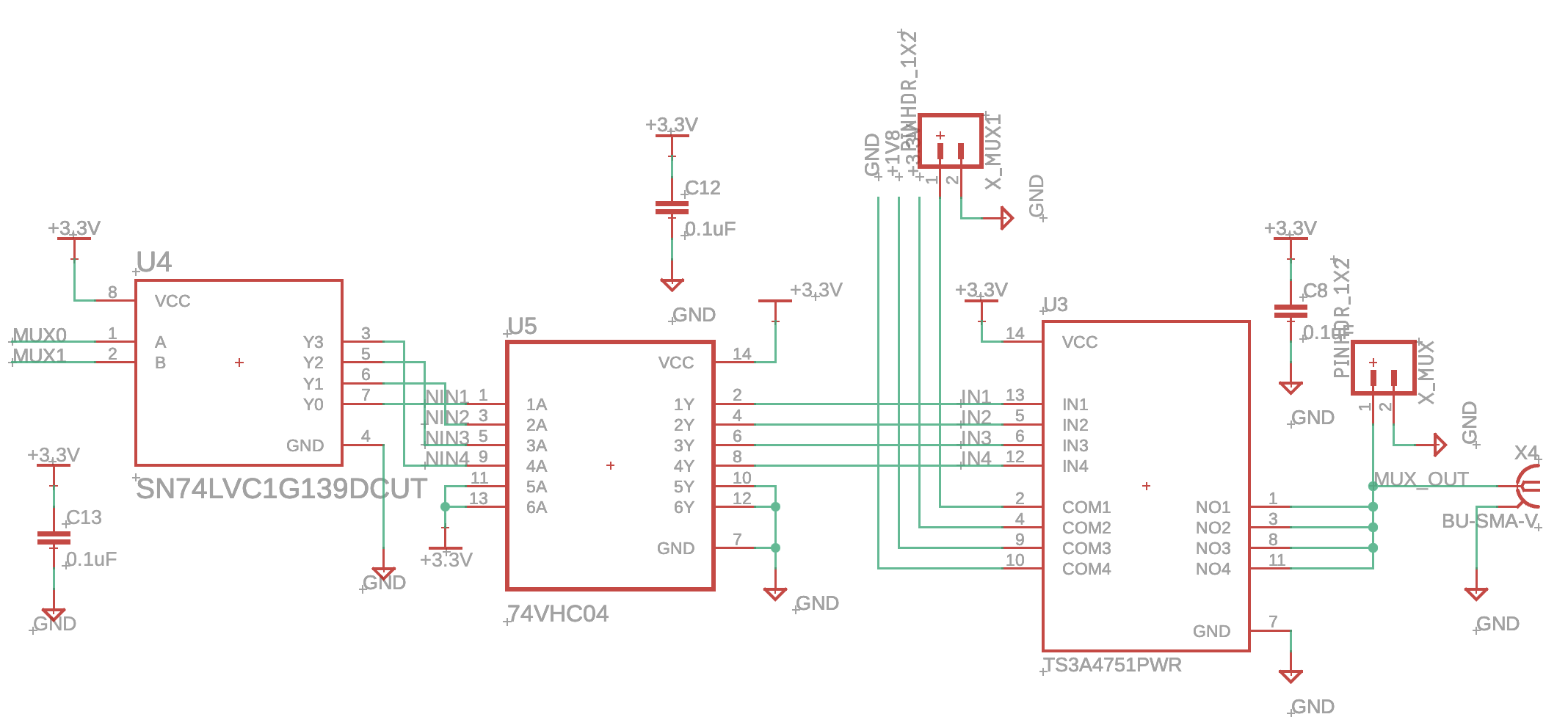
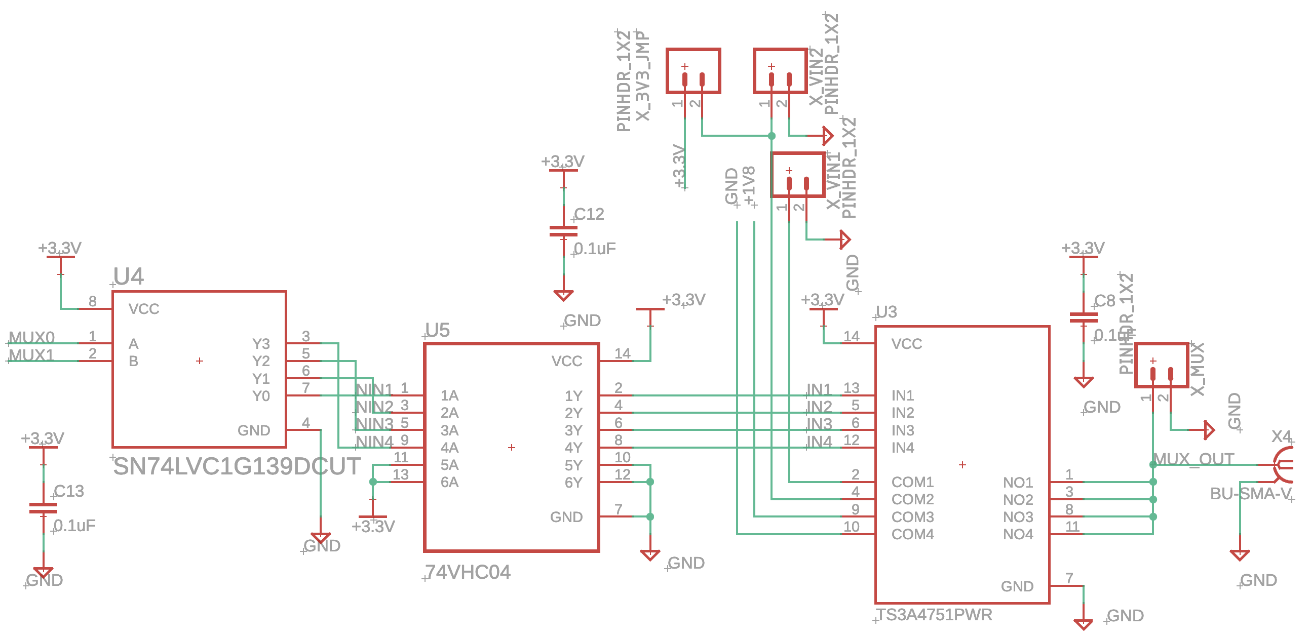
In order to switch quickly between different voltage levels, the chip TS3A4751 from Texas Instruments is used. This chip is a 4-channel analog switch in SPST (single-pull-single-through) configuration.
To make the analog switch easier to control and to reduce the signal lines from the Raspberry Pi Pico to the analog switch, a digital demultiplexer is used (SN74LVC1G139DCUT). Since the voltage levels are reversed after the demultiplexer, a 4-channel not-gate is used to reverse the voltage levels.
Multiplexing schematic for the Pico Glitcher v2.1 and v2.2:
Multiplexing schematic for the Pico Glitcher v2.4 and later:
This setup seems rather complicated to switch between four different voltage levels. However, the choice of analogue switches is not exactly extensive or does not match the requirements of a fast-switching fault-injection device. The required properties of the analogue switch are as follows:
- Fast switching: less than 5ns switching time.
- Number of channels: four channels for flexible switching between as many voltage levels as possible.
- Low resistance: to avoid switching losses, a low resistance of 1Ω or less is required.
- High output current: a high continuous current of at least 100mA is needed to keep the device powered even for a long time. This maximum current should be suitable for most microcontrollers.
All these requirements are met by the TS3A4751, even if the choice of this chip has made controlling it a little more complicated.