Schmitt Trigger EXT inputs
The trigger inputs EXT1 and EXT2 are particularly useful for noisy logic signals, as the noise can be easily suppressed by the adjustable Schmitt Trigger. If the signal oscillates or is disturbed in any other way, these disturbances can be filtered by selecting a suitable threshold.
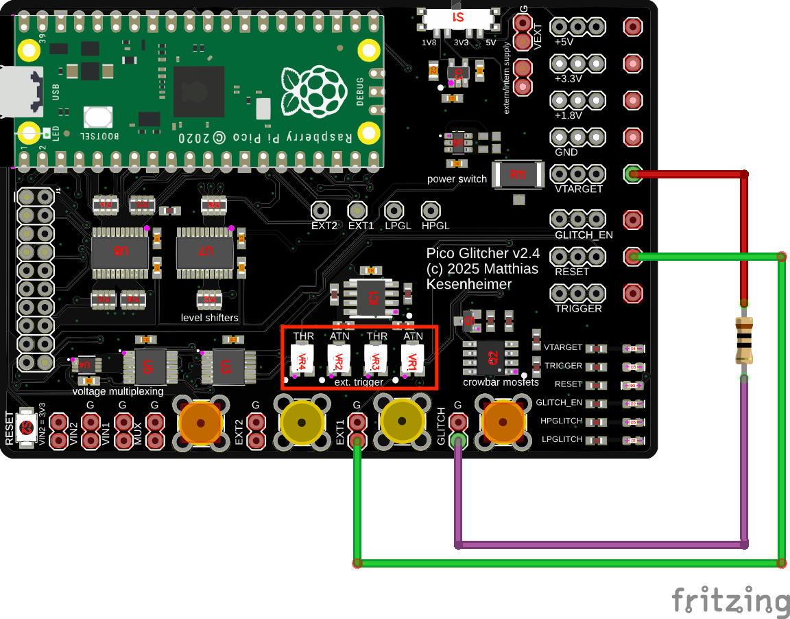
Use the potentiometer labeled THR to adjust the threshold of the Schmitt Trigger. The threshold is lowered by turning the potentiometer counter-clockwise.
The potentiometer ATN can be used to attenuate the signal, if necessary. Turning the potentiometer clockwise disables attenuation and uses the full signal range.
Changes have been made in version 3 to the EXT2 trigger input. Now the hysteresis of the trigger behavior can be adjusted.
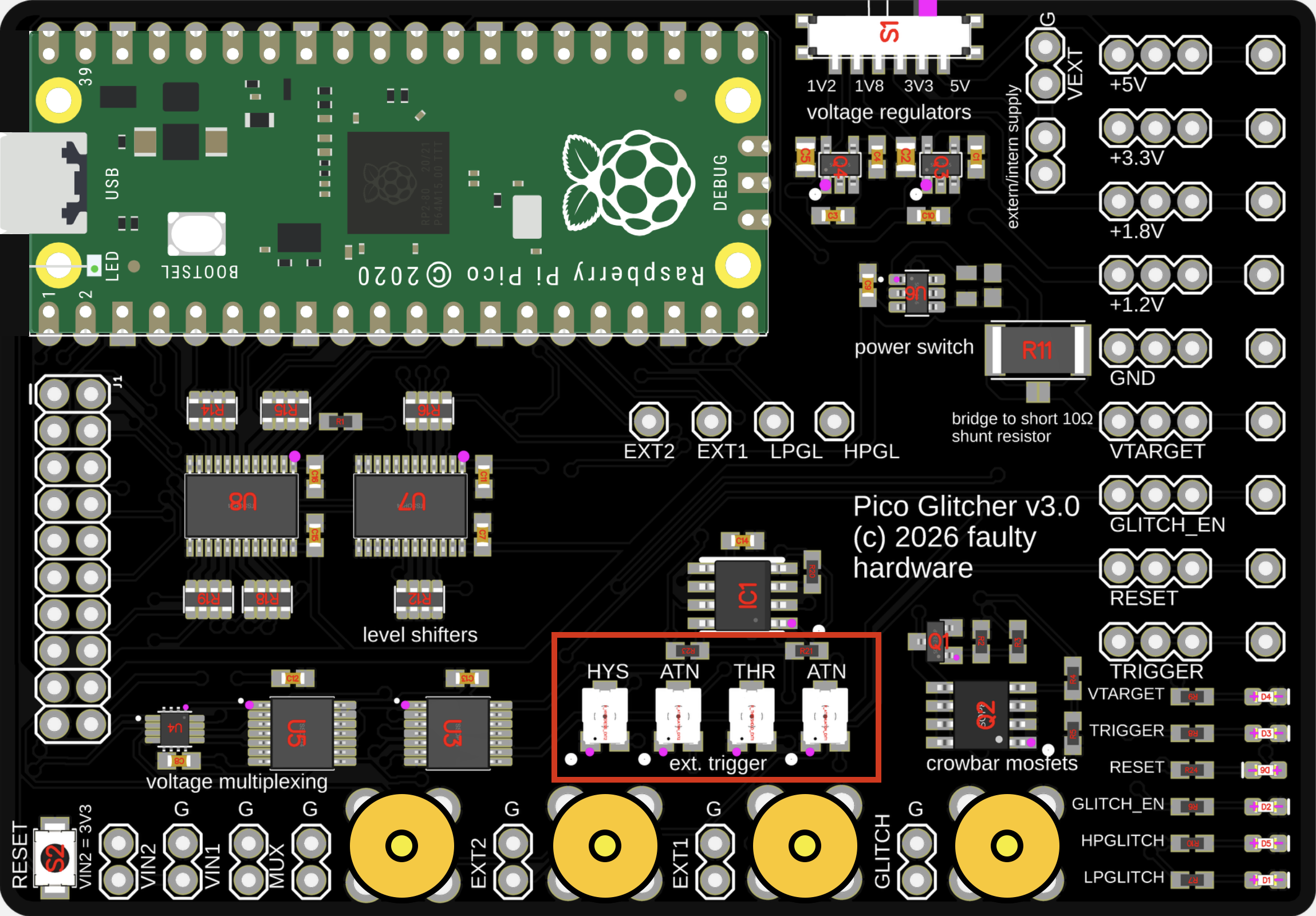
The HYS potentiometer adjusts the hysteresis of the Schmitt trigger input EXT2. It controls the difference between the upper and lower switching thresholds. A larger hysteresis means the input signal must change more before the output switches, while a smaller hysteresis makes the output more sensitive to small signal changes.
With no hysteresis, the Schmitt trigger switches at the same input level for both rising and falling edges. The output changes state exactly at a single threshold, making the circuit sensitive to noise and small fluctuations around that level.
When hysteresis is introduced, the switching point depends on the direction of the input signal. On a rising input, the signal must reach the upper threshold before the output changes, causing the transition to occur later than it would without hysteresis. On a falling input, the signal must drop below the lower threshold before switching back, which also delays the transition compared to a single-threshold comparator.
Increasing the hysteresis widens the gap between the upper and lower thresholds. This makes the circuit switch later on both rising and falling edges, relative to the no-hysteresis case. Reducing the hysteresis narrows this gap, bringing the two switching points closer together until they coincide when hysteresis is effectively zero.
This behavior is what gives the Schmitt trigger its noise immunity: small variations around the switching level do not cause repeated transitions, and the exact timing of state changes can be deliberately shifted by adjusting the hysteresis.
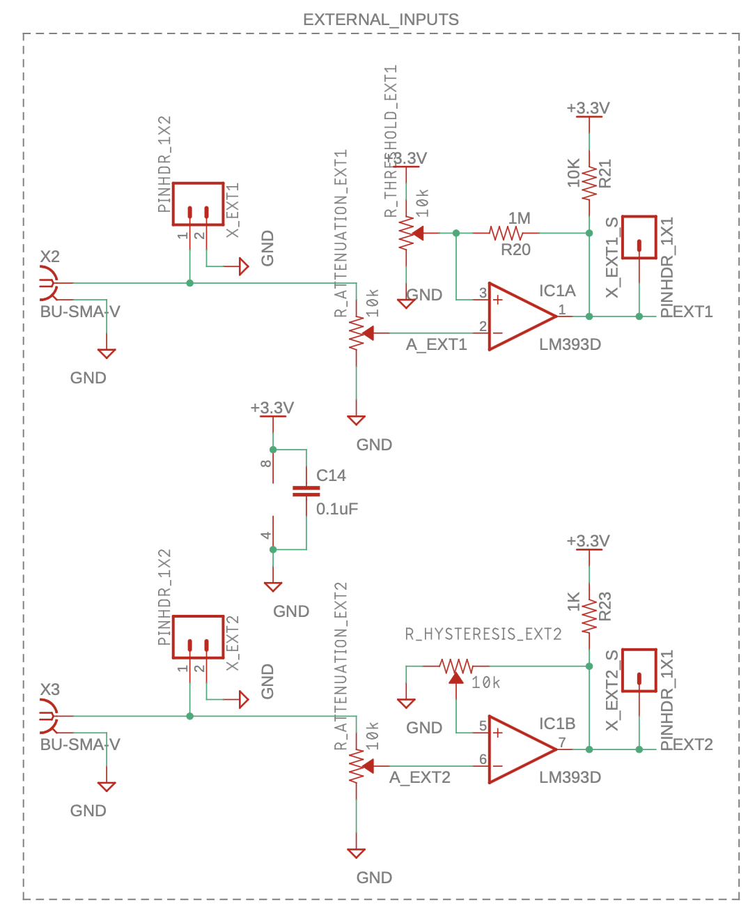
The schematics of the new Schmitt trigger inputs can be seen below.
How to set the potentiometers
The ATN potentiometer should be turned clockwise completely to the right to use the full signal range.
If you have trigger signals that exceed the voltage range of the Pico Glitcher (max. 5V), use the ATN potentiometer to attenuate the input signals to a range acceptable for the Raspberry Pi Pico.
By turning the THR potentiometer counter-clockwise to the left, the threshold is lowered, which means the Pico Glitcher triggers at lower signals. Start the THR potentiometer at the highest threshold position (right), then lower it (turn it counter-clockwise) until the trigger is observed.
Adjust the HYS potentiometer in the same way as the THR potentiometer. Start the HYS potentiometer at the highest hysteresis position (right), then reduce it (turn it counter-clockwise) until the desired hysteresis is achieved.
Choose the trigger input (EXT1 or EXT2) based on your setup and the quality of your trigger signal. Try each input to determine which works best.
Once the potentiometers are set for a particular configuration, do not change them during your glitching campaign. Changing the threshold or hysteresis values can affect your glitching parameters, particularly the delay value.